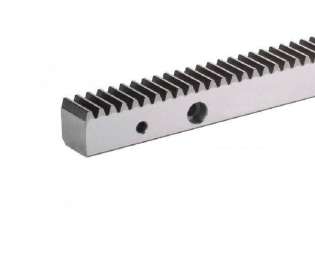
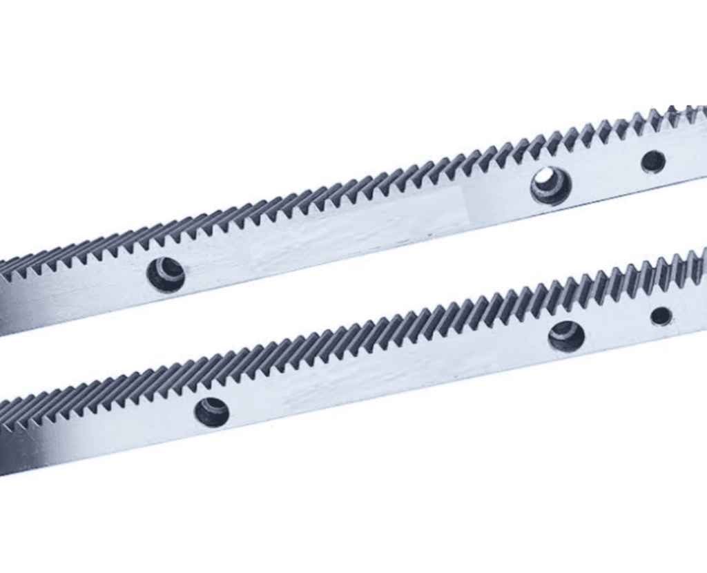
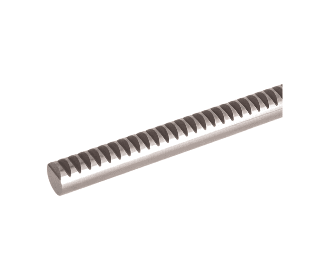
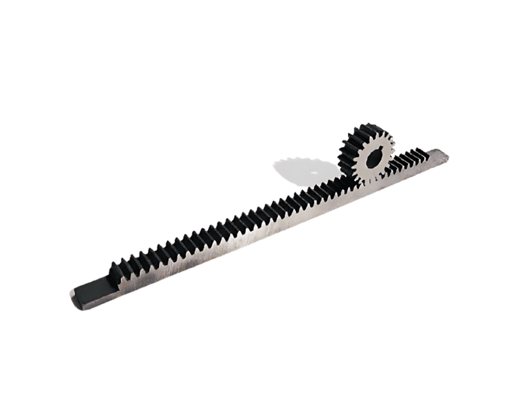
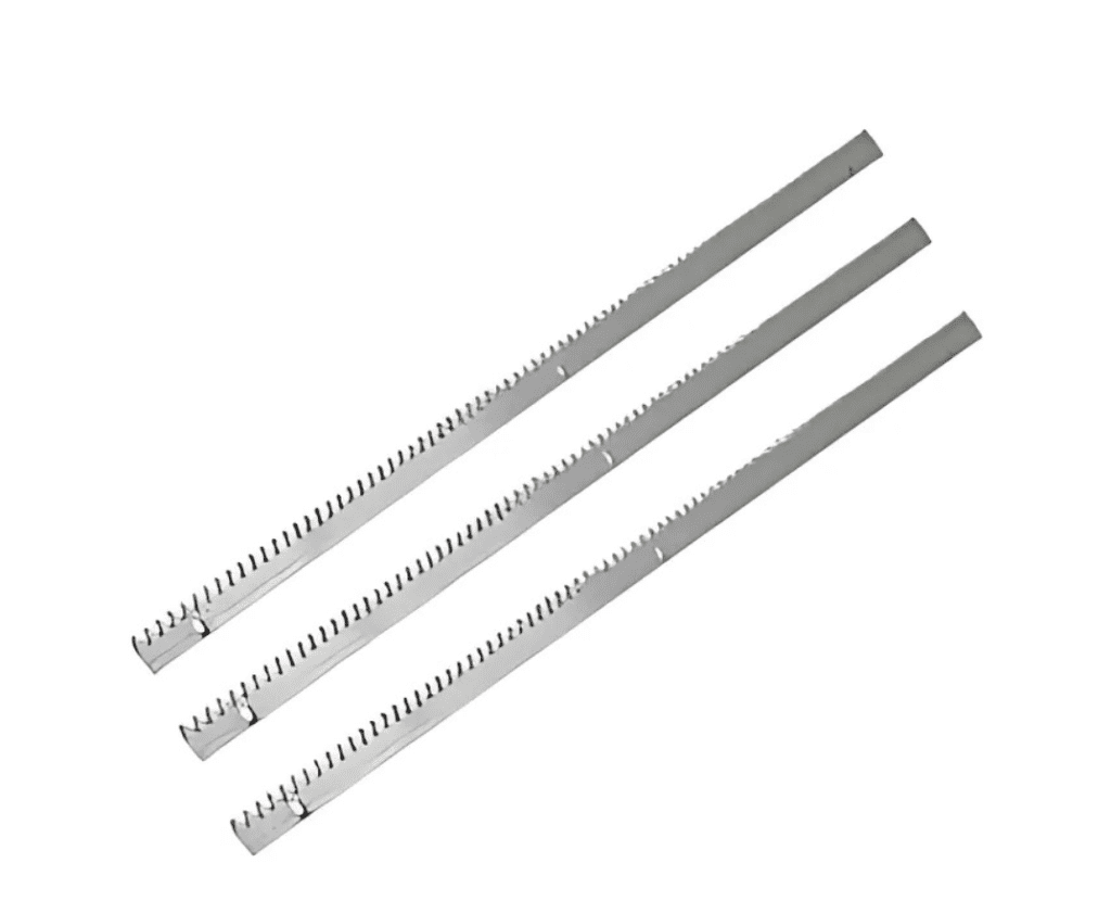
Kreymayer Stocks a Variety of Gear Racks to Accommodate a Wide Range of Rack and Pinion Configurations. We have Racks with Correctly Configured Tooth Forms at the Ends if the Application Requires a Long Length Requiring Multiple Gear Racks in Series. This is Referred to as “Gear Racks with Machined Ends.” When a Gear Rack is Manufactured, the Tooth Cutting and Heat Treatment Processes Can Cause it to Try and Go Out of True. We Can Control this with Special Presses and Corrective Procedures.
Gear Racks are Frequently Compared to Ball Screws as a Mechanical Element for Converting Rotary to Linear Motion. There are Benefits and Drawbacks to Using Racks Instead of Ball Screws. The Advantages of a Gear Rack Include its Mechanical Simplicity, Large Load Carrying Capacity, and Lack of Length Restrictions, Among Other Things. the Backlash, on the Other Hand, is a Disadvantage. A Ball Screw’s Advantages Include High Precision and Low Backlash, While its Disadvantages Include a Length Limit Due to Deflection.
There are Applications in Which the Gear Rack Remains Stationary While the Pinion Traverses, as well as Those in Which the Pinion Rotates on a Fixed Axis While the Gear Rack Moves. The Former is Commonly Used in Conveying Systems, Whereas the Latter is Useful in Extrusion Systems and Lifting/lowering Applications.
In Addition, We Also Offer a Wide Range of High-Quality Helical Gear Racks, Straight Teeth Ground Racks, Helical Teeth Ground Racks, Helical Hardened Racks, Helical Milled Quenched, Tempered Racks, Straight Hardened Rack, Straight Milled Quenched, and Tempered Ground Racks.
| Code | DIN 3962 | Material | Type | Teeth Treatment | Hardness | Mounted Holes | Module | Page |
| KCHRGH | DIN 5 | S50C | Helical Right Hand 19°31’42” | Teeth Ground | Hardened HRC 50°-55° | Holes | 1.5, 2, 2.5, 3, 4, 5, 6, 8 | P.6 |
| KCHRGH | DIN 6 | S50C | 1.5, 2, 2.5, 3, 4, 5, 6, 8, 10 | P. 7 | ||||
| KAHRG | DIN 6 | SCM440 | * | 1.5, 2, 2.5, 3, 4, 5, 6, 8 | P. 8 | |||
| KCHRM | DIN 8 | S50C | Milled | * | 1.5, 2, 3, 4, 5, 6, 8, 10 | P. 9 | ||
| KCHRMQ | DIN 8 | S50C | HRC18°-22° Quenched & Tempered | 1.5, 2, 3, 4, 5, 6, 8, 10 | P. 10 | |||
| KCHRMH | DIN 10 | S50C | Hardened HRC 50°-55° | 1.5, 2, 3, 4, 5, 6, 8, 10 | P. 11 | |||
| KCSRGH | DIN 5 | S50C | Straight | Teeth Ground | Hardened HRC 50°-55 | 2, 3, 4, 5 | P. 12 | |
| KCSRGH | DIN 6 | S50C | 1.5, 2, 2.5, 3, 4, 5, 6, 8 | P. 13 | ||||
| KCSRM | DIN 8 | S50C | Milled | * | 1.5, 2, 3, 4, 5, 6, 8, 10 | P. 14 | ||
| KCSRMQ | DIN 8 | S50C | Quenched&Tempered HRC 18°-22° | 1.5, 2, 3, 4, 5, 6, 8, 10 | P. 15 | |||
| KCSRMH | DIN 10 | S50C | Hardened HRC 50°-55° | 1.5, 2, 3, 4, 5, 6, 8, 10 | P. 16 |
| 1st | 2nd | 3rd | 4th | 5th | 6th | 7th | 8th |
| Material | Type | Shape | Teeth Treatment | Hardness | Module | Length | Grade |
| C | S | R | G | H | 020 | 10 | DIN JIS |
C= Carbon Steel =S50C A=Alloy Steel =SCM440 | S=Straight H=Helical | R=Rhombus | M=Milled G=Ground | H=Hardened Q=Quenched & Tempered | M1.5~M10 | 05=500mm 10=1000mm 15=1500mm 20=2000mm | DIN 5-10 JIS 1-5 |

